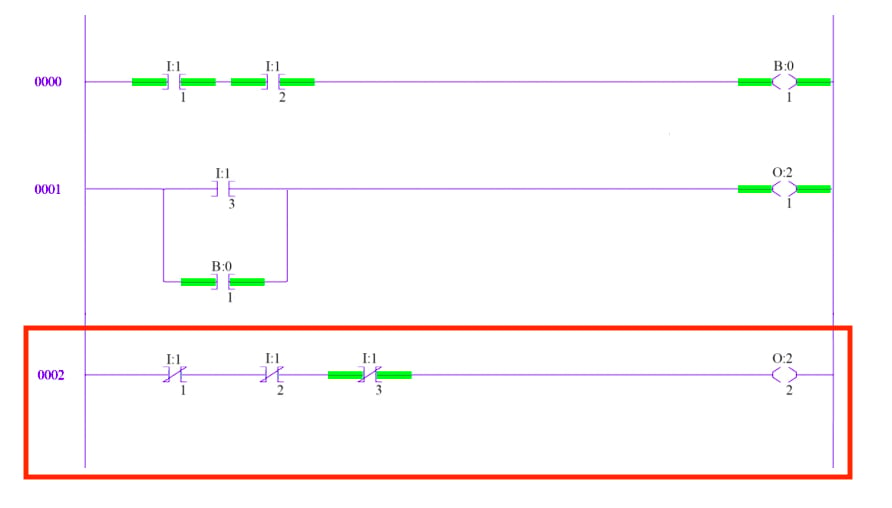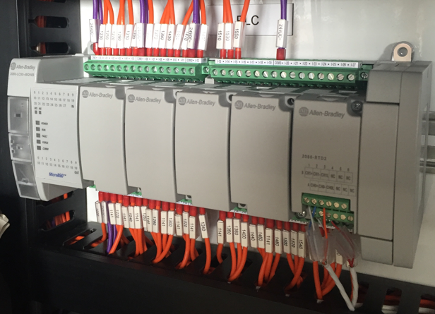
Ladder logic is widely used to program PLCs, where sequential control of a process or manufacturing operation is required. Part of a ladder diagram, including contacts and coils, compares, timers and monostable multivibrators

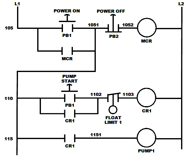
While ladder diagrams were once the only available notation for recording programmable controller programs, today other forms are standardized in IEC 61131-3 (For example, as an alternative to the graphical ladder logic form, there is also a language more like C called Structured text within the IEC 61131-3 standard). The name is based on the observation that programs in this language resemble ladders, with two vertical rails and a series of horizontal rungs between them.
PLC LADDER LOGIC WORLD SOFTWARE
Ladder logic is used to develop software for programmable logic controllers (PLCs) used in industrial control applications.

Ladder logic has evolved into a programming language that represents a program by a graphical diagram based on the circuit diagrams of relay logic hardware. In addition, other items external to the relay rack such as pumps, heaters, and so forth would also be shown on the ladder diagram. Each device in the relay rack would be represented by a symbol on the ladder diagram with connections between those devices shown. Ladder logic was originally a written method to document the design and construction of relay racks as used in manufacturing and process control. JSTOR ( May 2012) ( Learn how and when to remove this template message).Unsourced material may be challenged and removed.

Please help improve this article by adding citations to reliable sources. This article needs additional citations for verification.


 0 kommentar(er)
